
ISO-KF (ISO-QF) flanges are a standard choice for vacuum systems requiring quick assembly and repeatable sealing. Despite their widespread use, KF flange sizing can be a source of confusion during system design and component selection.
This article clarifies how KF flange sizes are defined, what the nominal size represents, and how to select the correct KF size based on system requirements rather than physical measurements alone.
What a KF Flange Size Represents
KF flange sizes are defined by a nominal bore, not by tubing outside diameter or flange outer diameter. Standard designations such as KF16, KF25, KF40, and KF50 describe the internal flow path diameter of the connection rather than a measurable external dimension.
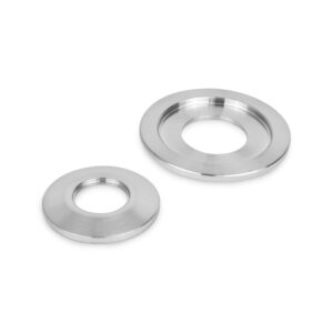
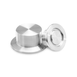
Because KF flanges follow ISO dimensional standards and the sealing interface relies on an elastomer O-ring captured in a centering ring with an external clamp, KF flanges of the same nominal size will mate regardless of manufacturer. Understanding this nominal sizing convention is essential when specifying flanges, clamps, and fasteners within a KF system. Considerations beyond tube sizing are discussed in detail below to assist in selection.


KF Size Selection: The Four Common KF Flange Sizes and Typical Use Cases
KF16 flanges are commonly used on small instrumentation lines, gauges, and compact vacuum assemblies. They are well-suited for applications where space is limited and mechanical loads are minimal.
KF25 is one of the most widely used KF sizes in general-purpose vacuum systems. It offers a balance between conductance and compact system layout, making it suitable for a broad range of laboratory and light industrial applications.
KF40 flanges are typically selected where increased conductance is required. They are often found on pumps, traps, and larger system interconnections, where proper alignment during assembly becomes more critical.
KF50 represents the upper practical limit of standard KF connections. It is commonly used in systems approaching the point where mechanical rigidity and load considerations begin to favor ISO-LF flanges.
Selecting the Correct KF Flange Size
When choosing a KF flange size, system designers will find success with the straightforward approach of matching tube inner diameter to flange size. Use the table below as a quick guide to match tubing inner diameter to the matching KF flange size.
| ISO Size | Tubing I.D. (mm) | Flange Size | Tubing O.D. (in.) |
|---|---|---|---|
|
NW10 |
10 |
QF10 |
0.50 |
|
NW16 |
16 |
QF16 |
0.75 |
|
NW25 |
25 |
QF25 |
1.00 |
|
NW40 |
40 |
QF40 |
1.50 |
|
NW50 |
50 |
QF50 |
2.00 |
|
NW63* |
63* |
QF63* |
2.50* |
|
NW80* |
80* |
QF80* |
3.00* |
|
NW100* |
100* |
QF100* |
4.00* |
|
NW160* |
160* |
QF160* |
6.00* |
|
NW200* |
200* |
QF200* |
8.00* |
*Non-standard QF sizes. This expanded size offering is available for QF Socket Weld Flanges.
Other considerations beyond tube size that influence flange selection such as frequency of assembly and disassembly, mechanical loading at the flange connection, or compatibility with existing vacuum components are design considerations weighed when choosing if KF flanges best suit your system needs over ISO, ASA, CF, or wire seal flanges.
Common KF Sizing and Selection Errors
KF flange installation errors most often occur when incorrect tube measurements are used to determine flange size. Always match the tube inner bore, or inner diameter, to the corresponding KF flange size and ensure the centering ring matches the selected flange.
Sizing confusion can also arise when comparing KF and ISO flanges at inner diameters above two inches (e.g., KF80 vs. ISO-LF80). This is typically the result of multiple fastening styles available at larger diameters. The hinged clamp design of KF connections can reduce stability and O-ring compression consistency as sizes increase, while ISO-K and ISO-F flanges use multiple claw clamps or bolts to provide greater rigidity and sealing reliability.
Although larger systems often transition to ISO flanges, reflecting the transition from flexible, serviceable connections to more rigid flange systems, KF connections remain ideal for applications requiring quick assembly and maintenance. ANCORP supports these applications by offering KF Socket Weld Flanges in expanded sizes that overlap with traditional ISO flange ranges, as shown in the sizing table above.
Proper sizing during design helps minimize leaks, misalignment, and premature component wear.
Final Thoughts on Specifying a KF Flange
Reliable KF sealing depends on proper system integration guided primarily by tubing size and influenced by system demands. ISO-KF flanges, compatible clamps, and correctly sized centering rings and elastomer seals must function as a matched assembly to ensure uniform compression and repeatable resealing. When selected and applied correctly, KF connections provide consistent performance across laboratory and light production environments.
Selecting these components in a complementary way to your system supports consistent sealing performance and repeatable assembly in both laboratory and production environments.