


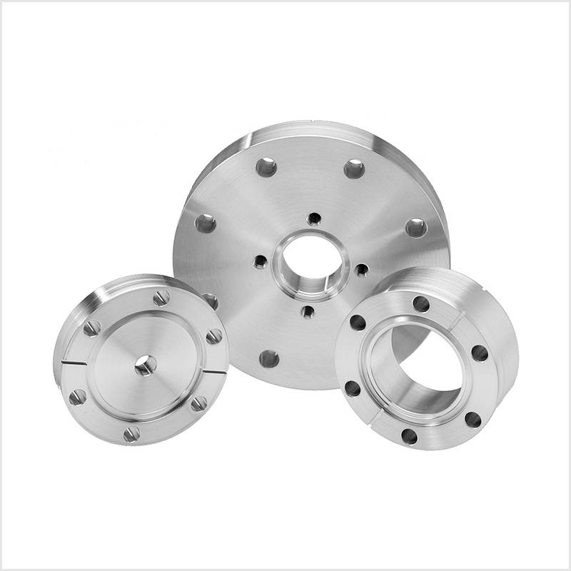
ConFlat flange (CF) UHV components are available in a full range of sizes (1.33″ to 16.50″ outer diameter), fixed and rotatable styles, and tapped or clearance (through hole) bolt hole configurations. Standard materials include 304L and 316LN stainless steel. Other materials such as 316L stainless steel and 6061 T6 aluminum are available upon request.
304L CF Flanges
304L ConFlat flanges are the industry standard for ultra-high vacuum (UHV) systems. 304L stainless steel has lower carbon content than 304 stainless steel, making it good for welding and offering better corrosion resistance than 304.
316LN CF Flanges
316LN ConFlat flanges are machined from electroslag remelt (ESR) low carbon, nitrogen-rich material. 316LN CF flanges feature low magnetic permeability and increased resistance to irradiation damage, crevice corrosion, and pitting.
ConFlat Multiport Flanges
CF Multiport Flanges are a unique UHV solution for integrating multiple devices to a single vacuum flange. Standard configurations are pre-specified for ease of customization with options for angled or straight-in ports with or without a central flange.
Special Purpose ConFlat Flanges
Special-purpose CF flanges host a variety of ConFlat flanges made to serve non-standard purposes. Here you can explore zero-length reducers, double-sided flanges, and flanges with NPT ports.
The ConFlat Flange System
The CF flange system provides a complete range of flanges to mount with tubing sized ¾” to 14” diameter. The CF seal assembly consists of two mating flanges, a sealing gasket, and fasteners to compress the gasket between two the two flanges.
CF Standard Sealing Assemblies
In a sealing pair of CF flanges, each contains an identical flange face with a knife-edge machined into the surface. A copper or FKM gasket is placed into the gasket capture groove of one of the two flanges. The flanges compress the gasket as the fastening bolts are tightened. This pressure forces the knife-edges of the two flanges into the gasket, creating an annular groove. The gasket material cold flows under this pressure and fills the microscopic surface imperfections on the sealing knife-edges, creating a vacuum-tight seal capable of withstanding temperature extremes from -200°C to 450°C and pressures as low as 1×10-13 Torr.
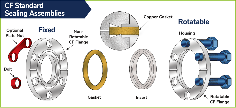
CF flanges are available in two general styles: fixed and rotatable. Fixed CF flanges have a set bolt hole orientation while rotatable flanges have a two-piece design allowing for bolt hole rotation to ease alignment when mating the two flanges.
CF rotatable flanges consist of two pieces: the insert (in which the knife-edge is machined) and the housing (in which the bolt holes are machined). When installing these components, the housing is placed behind the insert on the tubing prior to welding the insert to the tubing.
Both fixed and rotatable flanges are available with clearance (through) or tapped bolt holes. Clearance bolt holes are tightened with a nut on the back side of the flange assembly, whereas tapped bolt holes are threaded to receive and tighten the bolt directly into the flange.