


Designing a vacuum system rarely ends at the chamber wall. After pumps, gauges, and instrumentation are specified, the practical challenge becomes integration: routing lines through confined spaces, maintaining centerline alignment, and resolving the misalignment that inevitably emerges between concept and installation.
Vacuum fittings enable that integration. They translate layout intent into physical connections, accommodating geometry, port count, mechanical constraints, and the spatial realities of real-world systems. Standard fittings streamline assembly when configurations align with stocked dimensions, while flexible assemblies and custom solutions address vibration, thermal expansion, nonstandard angles, and multi-plane routing requirements.
This guide serves as a technical reference for engineers designing new builds or modifying existing vacuum systems. It begins by defining vacuum fittings and their role in system architecture, outlines key selection considerations, and progresses through the most common rigid fitting types (e.g., nipples, elbows, tees, and crosses), before addressing flexible assemblies, custom fabrication, and specification strategy to support efficient, serviceable system design.
A vacuum fitting is a component that connects two or more ports within a vacuum system. Connection interfaces may include vacuum flange standards such as ASA, CF, ISO, or KF; threaded connections like VCR or NPT; direct-to-baseplate mounting interfaces; or weld-prepped tube ends for in-house fabrication.
Vacuum fittings are typically selected to:
Additionally, vacuum fittings are not interchangeable across flange families. Each sealing system is engineered for a defined vacuum range and relies on a specific sealing approach, such as an elastomeric O-ring seal or metal gasket, along with its own material and compatibility requirements.
Fitting selection is governed by three primary factors: system geometry, availability and lead time, and cost.
System geometry is the primary driver for vacuum fitting selection. Precise evaluation of port angles, centerline alignment, bolt orientation, and spatial clearance ensures proper fit and simplifies installation. In retrofit or multi-vendor systems, misalignment between components is common. In these cases, fittings often provide the most efficient corrective solution without redesigning primary components or hardware.
Availability and lead time determine whether a standard catalog configuration can be used or whether custom fabrication is required. When port sizes, orientations, and offsets align with stocked offerings, standard fittings offer the fastest path to deployment. Nonstandard angles, reducing configurations, or multi-plane geometries may require additional engineering review and welding time.
Cost considerations are closely tied to fabrication complexity. Standard fittings generally offer the most economical solution, while custom geometries increase labor, inspection, and lead time. In some cases, modifying a vacuum fitting is more cost effective than redesigning a larger system component.
The sections below are organized by port count—covering two-port, three-port, and four-to six-port configurations—with guidance on when standard fittings are appropriate and when custom fabrication may be warranted.
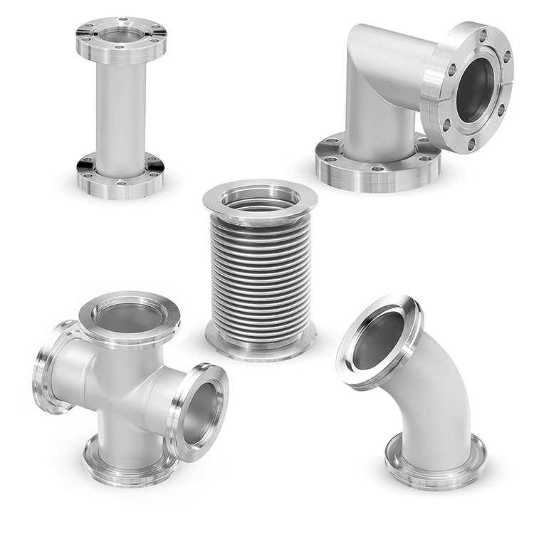
Nipples are straight sections of tubing with vacuum-compatible end connections, used to extend a line, adjust spacing between components, or maintain centerline alignment. They connect two ports along a single axis without changing direction, making them the simplest and most frequently used fitting in vacuum assemblies.
Common configurations include:
In rigid assemblies, nipples establish baseline spacing and alignment between components. In systems where thermal expansion, vibration, or motion must be accommodated, bellows or flexible hose assemblies may be introduced in place of rigid sections.
Due to their broad applicability across vacuum systems, standard nipple configurations are commonly stocked, with custom lengths fabricated when specific spacing or alignment requirements cannot be met with catalog options.
Elbows connect two ports through an angled section of tubing, allowing a vacuum line to change direction within the system. Standard bend angles include 45°, 90°, and 180°, with custom angles available for specialized layouts.
Common elbow configurations include:
Elbows are frequently specified to accommodate directional changes in tight layouts or to correct centerline misalignment without requiring modification of the chamber or mounting hardware.
As with all fittings, material selection, flange standard, and port size determine the applicable vacuum range and sealing compatibility. Special dimensional and performance details are outlined within the corresponding product categories.
Vacuum tees add a branch connection to a straight run, joining three ports within a single fitting. They are commonly used to integrate pumps, gauges, valves, or instrumentation without redesigning the primary chamber or introducing a separate manifold assembly.
Common configurations include:
Branch orientation, which distinguishes the straight-through run from the perpendicular run, is important for maintaining intended centerline alignment and system layout.
In pump stations, tees allow multiple pumping stages to tie into a single chamber interface. In analytical or coating systems, they provide access points for monitoring, gas inlet, or process control lines while preserving the primary flow path.
Adapter and custom tee configuration support mixed flange standards or non-standard spatial requirements when standard geometries do not align with the system layout.
Vacuum crosses consolidate four or more ports together at a single junction, creating a centralized connection point within the system.
Common configurations for crosses include:
In practice, crosses function as compact manifold points in systems where multiple lines converge—such as pumps, gauges, gas inlets, and sample ports—while reducing overall footprint, limiting the number of individual joints, and minimizing potential leak points.
Standard crosses are typically stocked in common flange types and sizes. Reducing crosses and custom multi-port configurations are used when mixed port sizes or specific spatial orientations are required. As port count and geometric complexity increase, fabrication and inspection time increase accordingly.
For layouts requiring more than six ports or involving non-orthogonal geometries, a dedicated engineered manifold assembly is often the most efficient and serviceable solution.
Rigid fittings resolve most routing challenges, but certain system conditions require flexibility. Bellows and flexible metal hose assemblies are used when axial movement, thermal expansion, vibration, or minor misalignment must be accommodated while maintaining vacuum performance.
Vacuum bellows provide limited axial compression and extension, making them well suited for correcting small centerline offsets and reducing mechanical stress at flange interfaces. They are often installed near pumps, valves, or chambers where thermal cycling or vibration is expected.
Flexible metal hoses offer greater lateral and angular compliance over longer distances. They are selected when rigid alignment is impractical or when vibration isolation is required across an extended run.
Both bellows and hose assemblies are available with standard vacuum flange terminations and are chosen based on vacuum range, bake-out requirements, allowable movement, and mechanical loading conditions. While rigid fittings establish system geometry, bellows and flexible sections introduce compliance where mechanical tolerance or dynamic operation demands it.
Standard fittings resolve the majority of vacuum routing challenges. However, custom fabrication becomes necessary when system geometry falls outside catalog limitations, such as nonstandard angles, mixed flange standards, multi-plane alignment requirements, or port counts beyond conventional cross configurations.
Custom fittings are most often required in:
Providing clear dimensional data (e.g., flange standards, centerline offsets, and spatial constraints) helps streamline engineering evaluation and fabrication. Supplying CAD models further accelerates quoting and reduces revision cycles.
In many cases, a thoughtful combination of standard fittings can achieve proper alignment with minimal modification, offering the fastest and most economical solution. Custom fabrication is typically reserved for situations where no standard configuration can meet functional or spatial requirements.
Efficient vacuum systems rely on precise connection strategy. Whether selecting stocked nipples, elbows, tees, and crosses or defining a custom multi-port geometry, fitting configuration influences installation efficiency, conductance performance, and long-term serviceability.
Careful evaluation of layout constraints, vacuum range, and mechanical considerations helps ensure the selected configuration supports both immediate integration and future maintenance.
Explore ANCORP’s standard vacuum fitting catalog(s) below or consult with our sales engineering team to review your layout and identify the most effective solution for your system.